

Chen Chao
(China Petrochemical Engineering Construction Co., Ltd., Beijing 100101)
[Abstract]: This paper elaborates on the significance and update status of API618 standard, compares the differences between API 618 Version 5 and Version 6 in detail, and interprets them based on engineering practice. API618 Version 6, after 16 years of summary and improvement, has proposed many new design concepts and requirements, making the standard more in line with engineering reality and providing better reference for practitioners in selection and design. The main updated points include exhaust temperature, reverse angle, and pulsation analysis method, etc. At the same time, some requirements in the new version have not yet been applied in actual engineering, and further consultation, detailed study, and gradual adaptation are needed in the future.
[Keywords]: API618; Reciprocating Compressor; API Standard
Chinese Classification Number: TH457; Document Code: B
Article Number: 1006-2971 (2025) 06-0037-07
1. Introduction
API618 "Reciprocating Compressors for the Petroleum, Chemical and Natural Gas Industries" (hereinafter referred to as API618) is a specification compiled by the American Petroleum Institute regarding lubrication systems, shaft seals, oil control systems and auxiliary equipment used in the petroleum, petrochemical and natural gas industries.
The version currently most widely used is API618 - 2008 (5th Edition) [1], and API618 - 2024 (6th Edition) [2] was officially published in 2024. It proposed many new design concepts and requirements, and compared with the 5th Edition, there were significant changes. This article focuses on comparing the important changes between the 6th Edition and the 5th Edition, and analyzes and interprets them in combination with engineering practice.
2. Interpretation of Key Changes
2.1 Scope
The applicable scope section of the 6th edition of API618 has been newly added: This standard does not apply to diaphragm compressors.
2.2 Terms, Definitions, Abbreviations
(1) New term: Certified Point, applicable to the working point within the performance tolerance.
(2) The combined rod load in the 5th edition has been changed to cross head pin load. Both are merely name modifications, and the term definitions have not been changed. They both refer to the algebraic sum of the horizontal force generated by the gas force and the reciprocating inertia force at the cross head pin.
(3) The rod reversal in the 5th edition has been changed to crosshead pin reversal. The modified definition is more accurate, representing that the force at the piston rod at the cross head pin has changed from tensile stress to compressive stress or from compressive stress to tensile stress.
(4) New term: Gas Load, the force resulting from the pressure difference between the two sides of the piston.
(5) New term: Inertia Load, the force resulting from the reciprocating motion of the components due to acceleration or deceleration.
(6) The maximum allowable continuous combined rod load and the maximum allowable continuous gas load in the original 5th edition have been deleted.
(7) New term: Rolled Thread, a processing method of forming threads on the workpiece by rolling with a forming tool. The processing method of rolled threads has the characteristics of high finish, high precision, and high strength. In engineering, it is generally required that the threads of the piston rod be rolled, thereby improving the connection reliability between the piston rod and the cross head.
3. Basic Design
(1) The 5th edition requires that the design and construction life of equipment and auxiliary equipment should be at least 20 years, and the uninterrupted operation should last for at least 3 years. The 6th edition removed these regulations and changed them to recommendations that only equipment that has been certified on-site is acceptable (the on-site certification is defined by the buyer), and it also recommends that the seller provide documents to prove that the supplied equipment has passed on-site certification.
(2) The 6th edition added a new requirement. If there is no on-site certified equipment, the seller can submit an explanation to explain that the provided equipment can be regarded as on-site certified, for example, it can be explained as: although the entire machine has not been on-site certified, the components that make up the entire machine are all on-site certified.
(3) The 6th edition added a new requirement. The seller should provide the lifespan of all components designed for limited life in the quotation. The revised API standards in recent years have all added the requirement to provide the lifespan of limited-life components, replacing the original 3-year uninterrupted operation requirement. However, in recent engineering projects, most still follow the 3-4 year uninterrupted operation requirement.
(4) In Table 2—Drive Trip Speed Table of the 6th edition, the trip speed of the constant-speed motor was changed from 100% of the maximum continuous speed to 102% of the maximum continuous speed. The main reason for this modification was to consider a 2% frequency fluctuation of the power grid. Since the motor is connected to the power grid, it is limited by the power grid frequency, and the motor generally does not exceed the speed, but the speed will change with the frequency. The design of moving parts such as piston rods, valve designs, and crankshaft designs all need to consider the change in speed. Therefore, the trip speed of the constant-speed motor was increased, equivalent to raising the design upper limit of the unit.
(5) In the 5th edition, it was required that after the equipment installation, the performance of the unit should be the responsibility of both the buyer and the seller. There are many factors that can have adverse effects on the on-site performance, including pipeline load, alignment during operation, support structure, handling during transportation, and on-site installation; to reduce the influence of these factors, the seller should review the buyer's pipeline drawings and foundation drawings according to the plan; the seller's review should be limited to the drawings of anchor bolts or the foundation drawings based on the seller's data. The 6th edition deleted these two requirements. In actual engineering projects, the design party still issues engineering drawings based on the manufacturer's data, and some of them will still be submitted to the manufacturer for review, such as the single-line diagram of pipelines with a preliminary support scheme used for the computer simulation analysis of pulsation by the manufacturer.
(6) The 6th edition added a new requirement. The external threads used for hydraulic stretching must have a protective cover on the exposed threads. In engineering, the connection between the piston rod and the crosshead, and the connection between the piston rod and the piston mostly adopt the method of hydraulic stretching connection, because hydraulic stretching requires a complete thread, and in order to protect the exposed threads, a protective cover is needed.
(7) Regarding the allowable emission temperature of gas, the 6th edition changed all the specified maximum expected emission temperatures under the operating conditions in the 5th edition that should not exceed 150°C to not exceed 135°C, and changed the expected emission temperature of the hydrogen-rich medium under the condition of molecular weight ≤ 12 to 120°C. The reduction of the expected emission temperature limit may lead to the compression process that could be completed in 3 stages in the original case now having to be carried out in 4 stages, adding a set of inter-stage cooling and separation equipment, increasing the unit investment and design difficulty. (8) In the 5th edition, it was suggested that the shutdown setpoint for the compressor exhaust temperature should not exceed 180 ℃. In the 6th edition, this was changed to no more than 175 ℃.
(9) In the 5th edition, the following rule was stipulated regarding the reverse force on the crosshead pin: When the crosshead pin bushing is verified and should be in a reliable form (such as a bushing with grooves), and the reverse angle of the force on the crosshead pin is at least 15 °, and the reverse force is at least 3% or more of the maximum force in the other direction. For some simple crosshead pin bushings (such as those without grooves), the reverse angle requirement should be at least 45 °, and the reverse force should be at least 20% or more of the maximum force in the other direction. Manufacturers should provide the actual values to the buyers during the quotation stage. In the 6th edition, the reverse angle and the maximum reverse force value are no longer specified based on the form of the crosshead pin bushing. They are uniformly stipulated as the reverse angle of the force on the crosshead pin should be at least 15 °, and the reverse force should be at least 3% or more of the maximum force in the other direction. This modification reduces the requirement for the reverse angle. In actual engineering design, due to insufficient reverse angle causing the lack of lubrication of the crosshead pin bushing, failure cases occur occasionally. Therefore, the requirement of reverse angle not less than 45 ° is still followed in the design process.
(10) In the 5th edition, it was required that the compressor should be able to withstand 110% of the maximum allowable crosshead pin load (combined piston rod load) or gas load within a short period of time. The overload time should be limited to within 30 seconds, and the frequency of occurrence should not exceed twice within 24 hours. In the 6th edition, this requirement was deleted. In previous engineering designs, to be conservative, it was required that the maximum crosshead pin load during normal operation should be 85% of the maximum continuous allowable crosshead pin load because the 6th edition deleted the requirement for the short-term overload capacity of the crosshead pin. In future engineering designs, the reserve capacity of the crosshead pin load during normal operation may be further increased.
(11) In the 5th edition, it was suggested that the seller should conduct a dynamic study on the valve to optimize the movement, impact and efficiency of the valve components. This study should consider the density and force conditions of all operating gases, and the assumptions used should be explained in the report. In the 6th edition, this requirement was changed to a mandatory item. In engineering practice, major brand valve manufacturers usually conduct dynamic studies on valves.
(12) In the 5th edition, it was required that the manufacturer should ensure that the preload force of the fastening bolts for the connection of the piston rod to the crosshead is equal to 1.5 times the maximum allowable continuous rod load. In the 6th edition, this was changed to the manufacturer should ensure that the preload force of the fastening bolts for the connection of the piston rod to the crosshead is equal to 1.5 times the maximum allowable continuous rod load minus the inertia force of the crosshead. The reason for subtracting the inertia force is that the piston rod and the crosshead move in the same direction, and their accelerations are consistent, so the inertia force does not need to be considered. If the inertia force is considered, it may cause over-tightening, increasing the fatigue failure risk at the connection point.
(13) In the 6th edition, a new regulation was added that the support ring should not exceed half of the width of the single-hole valve port or the chamfered width of the cylinder liner. When the cylinder configuration causes the support ring to exceed half of the valve port width, the valve design should adopt a multi-hole design to provide sufficient support for the support ring. The purpose of this new requirement is to provide more support for the support ring, increase the contact area between the support ring and the cylinder liner, and prevent the skewing of the support ring. (14) The 6th edition has unified the material selection standards for wet hydrogen sulfide environments from the 5th edition's NACE MR0175 to NACE MR0103. NACE MR0175 is applicable to exploration and production operations in the upstream of the oil and gas industry, including downhole and surface facilities of oil and gas fields, as well as factories for desulfurizing natural gas in environments containing H2S. It provides recommendations and stipulates requirements for selecting and identifying metals and alloys used in oil and gas production equipment. NACE MR0103 is specifically for downstream refineries, applicable to the processing conditions of acidic petroleum and similar conditions, which contain liquid or gaseous H2S.
(15) The 6th edition adds a requirement that the spun threads should be spun after heat treatment.
(16) In the 5th edition, it was required that if the main bearing used a rolling bearing, the L10 life of the bearing under the maximum axial and radial loads and the rated speed should not be less than 25,000 hours. The 6th edition increases the life to 32,000 hours. The L10 life of the bearing refers to the fatigue life that 90% of the bearings in a group of the same type can reach or exceed under standard test conditions.
(17) In the 5th edition, it was stipulated that for compressors with power exceeding 150 kW, the crosshead should be made of steel, and for those with power less than 150 kW, the crosshead can be made of ductile iron. The 6th edition modifies it to that the crosshead can be made of steel or ductile iron regardless of the compressor power.
(18) In the 6th edition, a new requirement is added that if the crosshead sliding bearing cannot be replaced or adjusted, it should be agreed by the buyer. Adjustable thickness crosshead sliding bearings can effectively adjust the alignment between the crosshead and the piston rod. During operation, due to wear or other factors, the alignment deviation between the crosshead sliding bearing and the slide channel may occur. By adjusting the thickness of the sliding bearing, the correct position of the crosshead in the slide channel can be ensured, reducing wear and vibration.
(19) In the 5th edition, it was suggested that the throat area of the pressure relief device of the crankcase should be no less than 70 mm2/dm3. In the 6th edition, this area requirement was deleted, and instead, if there are regulations, the crankcase should be equipped with one or more pressure relief devices to prevent rapid pressure rise of the crankcase. The selection of the device should consider the environment of the crankcase, oil mist or hydrocarbon gases, and the possible pressure rise of the crankcase.
(20) In the 5th edition, it was suggested that the cover plate of the middle body can be a solid metal cover plate, a metal mesh safety cover plate, or a metal louvre-style cover plate. In the 6th edition, the requirements were refined, stating that the metal mesh safety cover plate and metal louvre-style cover plate are only applicable to non-flammable and harmless gas conditions.
(21) In the 5th edition, it was required that the metal cover plate of the middle body should be able to withstand a pressure of 2 bar or higher in the cavity. The 6th edition increases the pressure-bearing capacity of the middle body cavity to 3 bar, and stipulates that if the design pressure of the middle body is less than the maximum operating discharge pressure, the seller should provide a solution. In engineering, the venting of the middle body is generally to the high point of the factory building, and it is generally not possible for the discharge pressure to exceed the design pressure. However, if the design pressure of the middle body is less than the maximum discharge operating pressure, safety valves should be set on the middle body. (22) In the 6th edition, a new regulation is added: For the middle section with two chambers, a buffer gas should be set in the inner middle section (the one closer to the crankshaft side), and the pressure of the buffer gas should be at least 0.5 bar or more than that of the outer chamber, in order to prevent toxic and harmful gases from the outer chamber from entering the inner chamber.
(23) In the 6th edition, a new requirement is added: The oil leakage rate of the oil scraper ring should not exceed 5 drops/
(24) The 5th edition suggests that when cooling the pressure packing, the seller needs to determine the minimum cooling flow rate, pressure, pressure drop, temperature, filtration, and corrosion protection, etc. The pressure drop of the cooling fluid in the pressure packing should not exceed 1.7 bar, and the temperature of the cooling fluid entering the pressure packing should not exceed 35 ℃. The 6th edition has changed this suggestion to a mandatory requirement.
(25) The 5th edition suggests that for all acidic and harmful gases, the cooling system of the packing should be separated from the cooling system of the cylinder jacket. The 6th edition has deleted this suggestion. In actual engineering, regardless of the nature of the compressed gas, the cooling of the packing and the cooling of the cylinder both use the same cooling system.
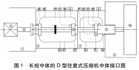
(26) The 6th edition adds a new buffer gas system requirement: the inlet pressure of the gas source entering the pressure packing should be at least 1 bar higher than the exhaust port pressure of port A (the exhaust port near the cylinder body) or port G (the exhaust port of the pressure packing), and the higher pressure of port A and G should be taken. This requirement is made to ensure that the buffer gas can smoothly enter the pressure packing without causing gas leakage in the cylinder.
(27) The 6th edition has refined the definition of low-temperature conditions. It is recommended that the buyer determine the minimum design metal temperature, which should be lower than the minimum ambient temperature and the minimum intake temperature. Consideration should also be given to possible throttling cooling conditions.
4. Design of Ancillary Equipment
4.1 Drive Mechanism
(1) In the 6th edition, it is required that for non-motor-driven compressors during the initial design, regardless of full-load or step-adjustment under partial-load conditions, the peak-to-peak unevenness of the rotational system's speed should not exceed 1.5% of the rated speed. However, in the 5th edition, there was no statement applicable only to non-motor-driven compressors, and the requirement was that regardless of the driving method, the peak-to-peak unevenness of the rotational system's speed should not exceed 1.5% of the rated speed. In practice, to reduce the rotational system's speed unevenness, it is necessary to first increase the rotational inertia of the system, and increasing the rotational inertia of the driving motor is the preferred solution to increase the overall rotational inertia of the system. Secondly, it is to increase the rotational inertia of the flywheel. If the compressor's driving method is an steam turbine or an internal combustion engine, it is basically impossible to increase the rotational inertia on the steam turbine or the internal combustion engine, and only the rotational inertia of the flywheel can be considered. In engineering, generally, the peak-to-peak unevenness of the motor's speed for motor-driven compressors should be less than 1% of the rated speed.
(2) In the 5th edition, it is required that the nameplate power of the motor (without considering the service factor) should be 105% of the power under the safety valve activation condition (including losses), and without considering the service factor, it should be no less than 110% of the power under all specified operating conditions (including losses). In the 6th edition, the consideration of the service factor was removed. Motors with a service factor greater than 1 can be overloaded temporarily. The modification of this clause is equivalent to lowering the requirement for the motor's nameplate power, allowing the motor to overload within the service factor range.
(3) In the 5th edition, it was suggested that if required, the starting torque of the motor should meet the requirements of the driven equipment. At 80% of the rated voltage (or the value specified by the buyer), the motor should accelerate from zero speed to full speed within 15 seconds (or within the agreed value by the buyer and the seller). In the 6th edition, this suggestion was deleted.
(4) In the 5th edition, it is required that for compressors driven by asynchronous motors, the fluctuation value of the motor current should not exceed 40% of the full-load current, and the calculation method uses IEC 60034 or NEMA MG1.
In the 6th edition, this requirement was deleted. Excessive current fluctuation can lead to thermal stress and harmonic losses, reducing the motor efficiency while increasing heat generation and accelerating insulation aging.
(5) In the 5th edition, it is required that when a synchronous motor is connected to the electrical bus of the existing synchronous motor, the buyer should conduct an electrical system analysis and provide it to the compressor manufacturer. In the 6th edition, this regulation was deleted. The reason for conducting an electrical system analysis when adding a new synchronous motor is mainly to verify whether the parameters of the new synchronous motor are compatible with the bus system and the existing motors, to prevent fault currents and optimize power quality and system performance. Engineers rarely encounter the situation of adding a new synchronous motor.
(6) In the 5th edition, it is required that for compressors driven by synchronous motors, the torsional stiffness and rotational inertia of all rotating components should ensure that any inherent excitation frequency of the compressor is at least 20% different from the torsional oscillation frequency of the motor rotor relative to the rotating magnetic field. In the 6th edition, this requirement was deleted.
(7) In the 5th edition, it is required that for motors without thrust bearings, they should have a permanent indication of the position of the rotor relative to the magnetic center line. In the 6th edition, this requirement was deleted. (8) In the 5th edition, it was suggested that the motor bearings should have insulation measures to prevent leakage current, the bearing seat should have adjustment pads, and the bearing box should have an oil seal to prevent the entry of dirt and moisture, as well as to prevent internal and external oil leakage. In the 6th edition, this suggestion was deleted.
4.2 Couplings and Coupling Guards
(1) In the 6th edition, a new requirement was added that the extended section of the coupling should be long enough to enable the removal of the flywheel or coupling hub without moving the motor. In practical engineering, whether for single-bearing or double-bearing motors, couplings still mostly use rigid couplings without an extended section. If the flywheel is to be removed, it is generally achieved through special structures or by moving the motor backward.
(2) In the 5th edition, it was suggested that the seller should provide guards for each coupling and all exposed moving parts. The guards should be removable without affecting the coupling. In the 6th edition, this suggestion was changed to a mandatory requirement.
4.3 Belt Drive
(1) In the 5th edition, it was required that if the power of the reciprocating compressor using belt drive reached 225 kW, the buyer's consent was needed. In the 6th edition, only reciprocating compressors with a power of less than 150 kW were allowed to use belt drive.
4.4 Lubrication
(1) In the 6th edition, it was required that if the compressor power was less than 150 kW and used rolling bearings, the pressurized lubrication system should follow the configuration requirements of Class I - P0 - R0 - H1 - BP0 - C1 F2 - C0 - PV0 - TV1 - BB0 in Table 1 of API614. If splash lubrication is used, it should be approved by the buyer. After the 2022 update of API614, it no longer distinguishes between general-purpose oil systems and special-purpose oil systems in chapters. Therefore, the requirement in the 5th edition that the pressurized lubrication system should follow Part 1 and Part 3 (general-purpose oil systems) of API614 was deleted.
(2) Regarding the instrument configuration of the oil station, the 6th edition requires that the oil system should have at least 1 level indicator (either on the crankcase or the oil tank), 1 low oil pressure alarm and a pressure transmitter for starting the auxiliary oil pump, 1 low oil level alarm transmitter for use as an alarm, 1 differential pressure alarm transmitter for the filter, and 1 low oil pressure interlock transmitter. The requirement of having to have 2 temperature transmitters as in the 5th edition has been removed.
(3) The 6th edition adds a new requirement that the return oil pipeline from the crankcase should be located above the maximum operating oil level. This is mainly to ensure a smoother return of oil.
(4) In the 5th edition, it was suggested that for all compressors with a power of 150 kW or more, the oil system should have an independently driven, full-flow, full-pressure auxiliary oil pump that can start automatically when the oil pressure is low and perform post-cooling after shutdown. The 6th edition has changed this to a mandatory requirement and added that the auxiliary oil pump should comply with API614 standards.
(5) In the 5th edition, there were many requirements regarding oil system coolers, oil system filters, oil system heaters, and oil system temperature control valves. The 6th edition has unified to delete these requirements and only requires that the corresponding components of the oil system should comply with API614 standards.
(6) In the 5th edition, it was required that the output power of the lubrication pumps for the cylinders and packing should be adjustable during the operation of the compressor, with an adjustment range of + 100% and - 25%. The 6th edition has changed + 100% to + 25% and reduced the adjustment range.
(7) In the 5th edition, it was suggested that the oil tank heater of the oil injector should have a temperature controller. The heating density should be limited to 2.3 W/cm2, and the size and temperature control instrument of the heater should be agreed upon by the buyer and seller. When using an internal heater, the oil level of the oil injector tank at the lowest point should also ensure that the heater is fully submerged in the oil. The 6th edition has changed this to a mandatory requirement and recommended that the oil injector tank should have a low liquid level alarm instrument and be linked to stop the heater when the liquid level drops to a certain extent.
(8) In the 5th edition, it was suggested that each oil injection system should have an oil injector failure alarm. The 6th edition has changed this to a mandatory requirement. In practice, the oil injector always has a pressure transmitter to monitor the outlet pressure of the oil injection system, thereby determining whether the oil injection system is faulty.
(9) The 6th edition adds a new suggestion that if specified, the oil injector tank should have an automatic floating oil filling device for replenishing oil. In engineering, multiple reciprocating compressors can be equipped with a high-level oil tank, and an automatic floating oil filling device can be used to automatically replenish oil to the oil injector tank, thereby reducing labor intensity.
4.5 Cylinder and Packing Cooling System
(1) The 6th edition adds a new requirement that the water tank should be equipped with: heater, vent port, level gauge, blow-off port, filling port, return port, pump suction port, inspection interface, and drainage port. The water tank heater should be electric or hot water or steam, and the heat loss of the water tank surface, cylinder, and pipeline and pipe fittings at the lowest environmental temperature should be considered.
(2) The 6th edition adds a new suggestion that if specified, the electric submerged heater should be able to be removed for maintenance during the operation of the cooling water system. If specified, a pipeline heater can be used. If this regulation is implemented, the electric heater should be indirect.
(3) The 6th edition adds a new requirement that the water system cooler should have exhaust and drainage ports in both the shell and tube sides.
(1) In Version 5, it was required that if the equipment weight exceeded 450 kg, three directions of locking nuts should be provided. In Version 6, this figure was changed to 225 kg.
(2) In Version 6, a new requirement was added that the seller should provide a projection drawing of the anchor bolts. The diameter of the bolt holes, the bolt layout, and the tightening force of each bolt should all be reflected in the layout drawing.
(3) In Version 6, requirements for the lifting ears of the overall baseplate were added. It was required that the maximum force of the lifting ears during lifting should not exceed one-third of the material's yield strength. The welds of the welded lifting ears should be in a continuous full penetration form and follow the AWS D1.1 standard. The welds should undergo 100% non-destructive testing. When all the equipment is lifted together with the overall baseplate, the baseplate should not undergo permanent deformation or damage to the equipment.
(4) In Version 6, a new requirement was added that the cavity of the overall baseplate should be filled with grout and sealed.
4.7 Control and Instruments
(1) In Version 5, the interlock and alarm of the related instruments were mandatory provisions, while in Version 6, they were changed to recommended configurations. In the alarm interlock table of Version 5, high exhaust temperature was an interlock item, while in Version 6, high exhaust temperature was changed to an alarm item, and alarm and interlock for crosshead vibration were added. This was the first time that API618 proposed the requirement for monitoring crosshead vibration. Because the crosshead is a component that moves in a straight line, it is relatively difficult to directly monitor its vibration. The existing vibration measurement methods are still carried out on the external cylinder of the crosshead liner. To more comprehensively monitor the vibration of the crosshead, generally, two vibration probes should be set at the left and right extreme positions of the crosshead operation.
(2) In Version 5, it was suggested to provide a probe for the downward movement of the piston rod while also providing a non-contact probe for the horizontal direction of the piston rod to monitor the horizontal displacement of the piston rod. And it was required that the piston rod probe should be close to the packing; equipment such as amplifiers should not be installed on the compressor. If the piston rod is coated, the probe of the piston rod should be calibrated. All the above suggestions were deleted in Version 6.
(3) In Version 5, it was recommended to set temperature monitoring for the crosshead pin bearings. This recommendation was deleted in Version 6. Because the crosshead pin is a moving part, it is very difficult to monitor its temperature. Wireless temperature measurement methods can be used.
4.8 Pipelines
(1) In Version 5, it was recommended that when the filter screen of the suction pipe for the process gas was provided by the seller, the design, location and orientation of the filter screen should be negotiated by both parties. In Version 6, this item was changed to a mandatory requirement, and it was required that the temporary filter for the process pipeline be provided by the seller.
(2) In Version 6, a new suggestion was added. If requested, the seller should provide the final outlet check valve. The form, size and position of the check valve should be determined by both parties. It is not recommended to use a swing-type check valve. This is because the exhaust of the reciprocating compressor is intermittent, and using a swing-type check valve may cause impact damage to the valve disc. In engineering, pneumatic valve-type check valves are commonly used.
4.9 Inter-stage coolers, post-coolers and separators
(1) In Version 6, a new requirement was added. The design of the water-cooled shell-and-tube cooler should follow TEMA class C or R. If TEMA class R is implemented, it should also follow the API660 standard.
(2) In Version 6, a new suggestion was added. The seller should provide the prefabricated pipeline from the compressor to the inter-stage cooler and post-cooler. In actual engineering, since the layout of the inter-stage cooler or post-cooler is designed by the designer, the pipeline from the compressor to the inter-stage cooler or post-cooler is generally provided by the buyer, but planned by the seller initially.
(3) In Version 6, a new requirement was added. If the gas processed by the cylinder is saturated or has become saturated, or if the temperature of the cylinder gas is within 10 ℃ of the expected dew point temperature, an independent separator (the separator is not integrated with the pulsation suppression device or cooler) should be set. If the gas temperature exceeds the expected dew point temperature by more than 10 ℃, an integrated gas-liquid separator can be used. In actual engineering, most multi-stage compressors, regardless of whether the temperature after cooling is within 10 ℃ of the gas dew point temperature, will have an independent gas-liquid separator. On one hand, it separates possible liquid precipitation, and on the other hand, it can collect the lubricating oil of the oil-injected compressor. Of course, some compressors that cannot liquefy oil do not need to have an inter-stage gas-liquid separator.
4.10 Vibration Analysis
(1) In Version 6, a new note was added. In variable conditions (such as changing the compressed gas, changes in operating conditions, or changes in loading steps), if analyzing all the combinations of working conditions' vibration analysis is not feasible, corresponding combinations can be reduced based on experience. In actual engineering, if the compressor is multi-unit and each unit has an air volume regulation system, the number of all working condition combinations is extremely large, and it is impossible to conduct vibration analysis for each one. Therefore, it is necessary to appropriately reduce the vibration analysis working conditions based on experience.
(2) Version 6 deleted Appendix O from Version 5: the preliminary selection procedure for low-pass filters.
(3) In Version 5, there were 3 vibration analysis methods: Method 1 (empirical formula method), Method 2 (acoustic simulation + pipeline constraint analysis method), and Method 3 (acoustic simulation + pipeline constraint analysis + mechanical analysis). In Version 6, Method 1 was deleted, and only Methods 2 and 3 were retained.
(4) In Version 5, it was required that for Method 2 or Method 3, during the preliminary acoustic simulation analysis of the pipeline system model, the maximum allowable pressure at the flange of the process pipeline side of the vibration suppression device should be considered. The pulsation values are specified as follows: When using a single pulsation suppression device, it is 80% of formula (8); when there are 2 or more pulsation suppression devices connected to the common pipeline, it is 70% of formula (8). In the 6th edition, there is no distinction between a single pulsation suppression device or multiple ones; it is required that the pressure pulsation value at the flange of the pipeline side of the pulsation suppression device be 70% of formula (8).
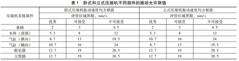
(5) The 6th edition adds a new requirement: The seller of the compressor should provide the allowable limit values for the vibration of compressor components, such as cylinders, frames, and crankcases. If the compressor manufacturer does not provide them, the guidance book on vibration of the unit by the European Reciprocating Compressor Association can be referred to. Historical versions of API618 did not have requirements for allowable limit values of vibration. This is the first time it has been proposed. This vibration limit has been synchronized to GB/T 41850.8 - 2022 "Mechanical Vibration - Measurement and Evaluation of Machine Vibration - Part 8: Reciprocating Compressor Systems".
(6) When calculating the pressure pulsation limit value at the connection point between the pressure pulsation suppression device and the process pipeline, the 5th edition requires that if the average absolute pressure in the pipeline is less than 3.5 bar, the pressure pulsation limit value should be considered based on the average absolute pressure of 3.5 bar. In the 6th edition, it is required that if the average absolute pressure in the pipeline is less than 3.5 bar, the pressure pulsation limit value should be considered based on 3.5 bar of the average absolute pressure multiplied by a coefficient. The specific formula can be referred to in formula (9) of API618 - 2024.
(7) When calculating the pressure drop of the pulsation control device (such as a orifice plate), the 5th edition requires that the pressure drop of the pulsation control device should not exceed 0.25 times the average absolute pressure of the pipeline, or the calculated value of formula (13), and the larger value should be taken. In the 6th edition, the calculation method is refined. If the pressure ratio is ≤ 1.4, the maximum pressure drop of the pulsation control device in the suction and discharge systems under steady state is 0.5% of the average pipeline absolute pressure. If the pressure ratio is greater than 1.4, it should be calculated by formula (13).
5. Inspection and Testing
(1) In the magnetic particle inspection section of the 6th edition, the maximum allowable residual magnetism requirement has been added.
(2) In the 6th edition, a new suggestion has been added: if required, the medium body should also undergo a hydrostatic test at 1.5 times the maximum allowable working pressure.
(3) In the 5th edition, it was required that the pressure for the hydrostatic test be 1.5 times the maximum allowable working pressure. Temperature compensation coefficients should also be considered, with the temperature compensation coefficient being the ratio of the allowable stress value of the material at the hydrostatic test temperature to the allowable stress value of the material at the rated operating temperature. In the 6th edition, the requirement for temperature coefficients has been removed because the operating temperature of reciprocating compressors is often below 150 ℃, and the temperature compensation coefficient below this temperature can be ignored.
(4) In the 6th edition, a new requirement has been added: if the temperature measurement elements of the main bearing and the packing are both supplied by the manufacturer, the corresponding temperature values should be recorded during mechanical operation, and the oil temperature, oil pressure, speed, and piston rod temperature should also be recorded during the mechanical operation test.
(5) In the 6th edition, a new suggestion has been added: if required, the vibration of the cylinder and the crankcase during mechanical operation should be recorded.
(6) In the optional tests of the 6th edition, a new suggestion has been added: if required, an oil discharge device for the cylinder should be installed and a functional test should be conducted.
6. Appendix
1) Appendix D of the 5th edition was deleted: Repair of gray iron castings or ductile iron castings.
(2) Appendix O of the 5th edition was deleted: Guidelines for the design of low-pass filters.
(3) Appendix P of the 5th edition was deleted: Guidelines for the shaking force of pipeline and pulsation suppression devices.
(4) Appendix Q of the 5th edition was deleted: Compressor components in accordance with NACE MR0175 standards.
(5) Appendix F of the 5th edition was refined: Requirements for seller's drawings and data, and the appendix name was changed to Contract Documents and Engineering Design Data.
(6) Due to changes in the pulsation analysis method, part of Appendix M of the 5th edition was refined: Work flowchart for design methods.
(7) Appendix I of the 5th edition was refined, reducing the mid-body exhaust, drainage and buffering system for process gas leakage, dividing the back pressure of mid-body exhaust into variable back pressure and constant back pressure, and refining the diagram of mid-body exhaust, drainage and buffering system.
7. Conclusion
The two versions of API618 - the 5th edition and the 6th edition - were released 16 years apart. After a long period of experience accumulation, the 6th edition has been revised and supplemented in aspects such as exhaust temperature, reverse angle, materials, current pulsation, and pulsation analysis methods, and some clauses have been deleted. Since the 6th edition was released less than half a year ago, in actual engineering applications in the future, it is necessary to gradually adapt to the relevant provisions of the new version in order to better guide engineering practice.
References:
[1] Reciprocating Compressors for Petroleum, Chemical, and Gas Industry Services: API 618 - 2024 [S] . Washington D.C.: API Publishing Services, 2024.
[2] Reciprocating Compressors for Petroleum, Chemical, and Gas Industry Services: API 618 - 2008 [S] . Washington D.C.: API Publishing Services, 2008.
Author Profile: Chen Chao, male, from Jinan, Shandong Province. He holds a master's degree and is a senior engineer. He graduated in 2014. Major in Chemical Process Machinery at China University of Petroleum (East China), currently engaged in the management of pumps and machinery in the petrochemical industry.
E-mail: chenchao.sei@sinopec.com